BULB TO LED CONVERSION INSTRUCTIONS
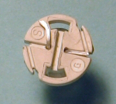
1. Remove the stock bulb from the plastic base by unwinding the two contact leads. You might need a used staple or something to pick the leads out of the grooves.
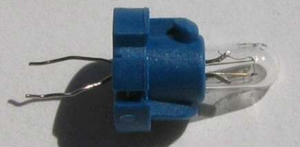

2. Now pull the bulb out of the plastic holder and insert the LED through the holes.
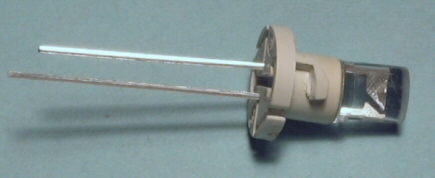
3. Note which side is the anode and which side is the cathode. Unlike regular bulbs, LED's are polarized and will not work if you plug them in the wrong way. The anode is the + lead and is longer than the other.

4. This step is ONLY for the LEDs that will be installed in the following:
98-02 Honda Accord
Clock
Sunroof button
Cruise button w/ TCS
Cruise button (no TCS)
Sunroof button
Fog light button
|
|
94-97 Honda Accord
Sunroof button
Cruise button
Dimmer button
Rear defrost button
|
|
99-03 Acura TL & 01-03 Acura CL
Clock
Sunroof button
Cruise button
Fog Light button
Reset / select button
|
01-05 Honda Civic
Sunroof button
Fog light button
Rear defrost button
|
|
97-01 Honda Prelude
Sunroof button
Cruise button
Dimmer button
|
|
|
|
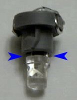
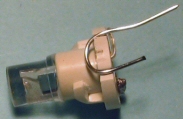
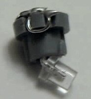
To make items listed above light up a little brighter, leave a small space between the plastic bulb holder and the bottom of the LED. The blue arrows are pointing to the space that was left. You might want to leave a bit more room than shown in the picture.
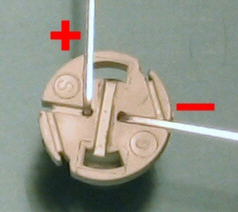
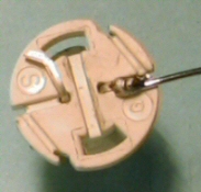
5. Bend the negative (-) lead so it goes into the groove. Bend the positive (+) lead 90° from the other groove and cut both leads so that they do not stick out past the bulb holder. It will help if you can bend the positive (+) lead slightly toward the end. (See right picture.)
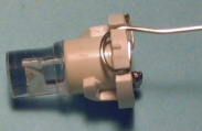
6. Solder one end of the wire (included with your kit) to the the negative (-) lead and wrap the wire around the bulb holder in the groove. The wire will go where the contact leads on the stock bulb were before you removed the bulb. Cut off any extra wire an put the end of the wire in the groove.
 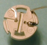 
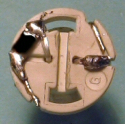
7. Take another piece of wire (included with your kit) and bend it in a "U" shape an put it on the bulb holder as shown in the left picture. Cut one of the ends short enough so it will fit down in the groove, and bend the wire into the groove. Next cut the other end of the wire and fold it into the same groove. It is OK if it overlaps the other end of the wire as seen in the picture on the right.
  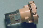
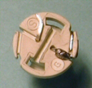
8. The left pictures shows what it should look like. Place a resistor (included in your kit) between the LED lead and the wire you just wrapped around the bulb holder and solder both sides of the resistor.
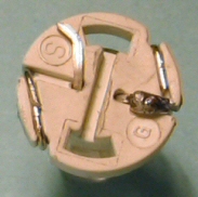 
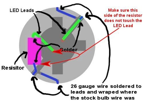
9. Here is a diagram that shows the layout of an LED correctly installed.
10. ONLY perform this step if you left a space between the LED and the plastic base as described in STEP 4.
Figure out which way the LED is to be installed. Put the LED assembly (the LED and base) in the button or clock to see if it lights up. If it does not light up, take it out and rotate it 180 degrees (1/2 a turn) and try again. Once you know which way it goes in, remove the LED assembly and bend the LED toward the front of the button or clock and reinstall it. You may want to play with the angle that you bend the LED to get the button or clock to light up as bright as possible.
*Important!* - While soldering, do not hold the soldering iron to the LED lead, resistor or the solder joint for more than 3 or 4 seconds. If the solder does not make a good contact, wait until it cools before heating it up again. If you hold the soldering iron on the solder joint too long, the resistor and/or the LED will become useless. The resistor will go out before the LED and we have included extra resistors in case you need them.
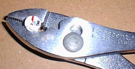
A trick to help you solder the tiny resistors on the bulb holder is to use your pliers to hold the bulb holder. Put a rubber band around the handle so it holds the bulb holder and use your tweezers to hold the resistor into place with one hand while you solder it with the other hand.
 | |
|

 LED Technology
 Automotive Kits
 Eco-friendly
 LED Types
  Multiple Colors